This is a reference video for a functioning Prometrix / Tencor OmniMap RS35. This video was taken after a rebuilt/repair on 36-0004 / 54-0005/ 54-0389 (Current Source), 54-0014 / 36-0014 (DVM card) and 36-0042 (Analog Power Supply). Note that all units from https://getspares.com/ will have a full function test in OEM tool before shipping. This in-tool verification applies to parts sent in for repair or going out as new to you. If you have an interesting issue or problem with your Prometrics, please contact us for help and send us a picture or video for future searchers.
Category Archives: Mapping, Probing & Scanning
KLA Tencor Prometrix UV1280 UV1050 Aligner Initialization
The following video shows the timing of the flat aligner movement an wafer want initialization during a power on sequence.
Depending on your error and timing of the fault, this video can help us determine what part may be faulty before sending it in for repair.
– from UV1250-UV1280 – PCB Stage Driver F2 Rev. F – 36-0287 54-0287 RevAG ,36-0294 – Turret Servo Driver 54-0294 – Servo Driver , 51-0175 H-2 Aligner – Motor Controller ,54-0384 PC interface card to talk to measurement board – PCIF ,PCB Measurement Control Board 54-0317 36-0317 , 54-0317REV2,PCB-8809A-B4 Com/Processor board from front card cage. – Ziatech Processor Board
If you have any questions or want to post videos or troubleshooting tips for this tool, contact us at info@comvolt.com. If you are looking for parts, https://www.getspares.com is a great place to start!
Prometrix RS-75 Simple Power on Sequence and Resistance Measurement
These videos server as a baseline for Prometrix RS-75 tool operation and troubleshooting. These runs use the standard test resistance modules also seen on RS35, RS55 and VP10e tools. Some boards that customers have problems with are the 36-0325 and 52-0616 controller and ME box.
When communicating issues and problems with your tool timestamps of these videos can help us understand the issues you are having. Take a look or send us pictures or videos of your specific issue.
KLA/Prometrix RS-35 36-0004 / 54-0005 Current Source With Beckman 7581
Compliance Errors and Measuement Errors on Your Prometrix OmniMap? Call https://www.getspares.com/
Custom Solutions Available!
KLA/Prometrix RS-35 36-0004 Current Source With Beckman
KLA/Prometrix RS-35 54-0005 Current Source With Beckman
KLA/Prometrix RS-55 54-0005 / 54-0005 Current Source With Beckman
KLA/Prometrix Versaprobe VP10e 54-0005 / 54-0005 Current Source With Beckman

chip overheats and causes measurement errors and compliance errors on RS-35 and RS-55
Prometrix/KLA Omnimap RS-35, RS55 Calibration Procedure 54-0014 36-0014 PCB DVM 36-0004 Current Source PCB 54-0005 or 54-0389)
____________ Testing the Analog Section ____________

CAUTION Call GetSpares before attempting any of the following as it might invalidate your warranty.
The Purpose of these instructions is to determine if a PCA board in the analog se‘sfi’zezd to tester has failed. The following section includes an overview of the tools you l ection of perform the test, as well as an overview of the PCA boards thatcompnse the ana 08 5 the tester.
Testing the analog section basically consists of the following:
Testing the Power Supply board.
Testing the Current Supply board.
Testing the Relay and Voltmeter boards.
Testing each board in the order just described enables you to determine of a particular board has failed.
If you are not familiar with Term4 software, refer to Using Term4 before proceeding with the following procedures.
Tools Required to Test the Analog Section a
You will need the following tools to test the analog section. b ‘1‘ 0
Fast response multimeter with 5 or 6 digit display (response time of 250 ms). 0
Clip—on type leads for multimeter. 0 p
5/32 allen wrench (ball type driver). 0
2.79 ohms/ sq. resistor network (part number 50—0009). 0
Term4 or MPTerm software. (Refer to Using Term4 if you are unfamiliar with Term4 software.) . . ‘
Important Remove the probe head from the tester before proceeding with these tests.
PCA Boards That Comprise the Analog Section
Follow this procedure to locate the PCA boards of the testers analog Section
1. Remove the right-side panel from tho tester to allow arrows to the Analog PCA’s.
2. Locate and Identify the four Analog PCAs in the tester. When looking at the card cage from the left side of the tester. The PCAs that comprise the analog section are located at the extreme left. The follwoing describes and gives the location of each board.
The Analog Relay PCA board is the far left position of the card cage. The probe head cable and two jumper boards are connected to the Analog Relay PCA. During measurements, this board sends currentl to and from the probe head. 0
The Analog Voltmeter PCA board is to tho right of the Analog Relay PCA. The Analog Voltmotor PCA shares the short four-pin jumper board with the Relay PCA. The Analog Voltmotor PCA makes the mweasurements, and converts analog to digital.
The Analog Current Supply PCA board to to tho right of the Analog Voltmotor PCA. The Analog Voltmetor PCA has a short five-pin jumper, and shares the long four-pln jumper with the Relay PCA. This board produces the current that is forced to the probe head during measuremnts.
Thu Analog Power Supply PCA board in to the right of tho Analog Current Supply PCA. The Analog Power Supply PCA shares the short five-pln jumpor with tho Analog Current Supply PCA. The Analog Power Supply may or may not (depending on tho age of your system) may have a two-pin connector at the top. Thatconnector connects to a battery which in used during measurements whoro the selected current is 20.0 mA or less
WARNING if your system has an Analog Power Supply with a battery connectormmrclor. NEVER connect or disconnect any of the jumper boards or any leads to the multimeter without turning off the tester and disconnecting the battery from the Analog Power Supply PCA.
If your system has an Analog Power Supply PCA without a batter connector , NEVER connect or disocnnect any of the jumber board or leads to the multimeter without turning off the tester.
Testing the Power Supply Board es . assum
The following procedures describe testing the Power Supply board. This procedure assumes you have already removed the right side panel of the tester. (Refer to .: Replacing the Left and Right Side Panels” in Chapter 4.)
To test the Power Supply board:
1. Power Off the tester and disconnect the two-pin battery connector (If your system has one) from the Power Supply board.
2. Disconnect the short five-pin connector between the Power Supply board and the Current Supply board.
3. Connect the Negative lead of the multimeter to the bottom pin of the five Pin connector on the Power Supply board.
4. Select VDC on the multimeter and power on the tester.
\— Note Use caution to ensure you do not short between pins when measuring voltages. . A
5. Verify the following voltages are being output from the Power Supply board.
6. Power off the tester. 1
7. Disconnect multimeter from the five pin output connector.
8. Power on the tester and measure the output of the two pin battery output connector to ensure that the output is approximately 13.8 vdc.
9. Measure the voltage from the battery at the connector that plugs into the Power Supply to ensure that it is approximately 13.6 vdc.
10. Power off the tester. ‘ a.
11. Connect the negative lead of the multimeter to the bottom pin of the five pin connector.
12. Connect the two pin battery connector to the Power Supply board.
13. Verify that there are no voltages present at the five pin connector Outputs.
If any of the above reading were incorrect, the Power Supply board is defective. Please contact GetSpares for further instructions. If all of the readings were correct, continue to the next step in this procedure. .
Table 7-10: Pins of the Power Supply PCA Board and their Voltage Outputs
Pin Voltage Output Acceptable Ranges
top pin of five pin output +50 vdc 48—50.00 vdc
next to top pin +20 VDC 18—20.0 vdc
third pin +15 vdc 1 15 +/- 0.25 vdc
second pin —15 vdc 15.00 vdc +/-.025 vdc
bottom pin analog ground .
Testing and Calibrating the Current Supply Board
The following procedure describes testing the Current Supply board. This procedure assumes you have tested the Power Supplyboard, and have determined thatitis functioning prOperly. If you are unfamiliar with Term4 software, read “Proper Format for Entering Commands in Term4.” Otherwise, proceed with the following instructions.
1mPortant The Current Supply is static sensitive. Take precautionary measures to prevent Static Electrical Discharges. Remove the probe head before proceeding with the calibration instructions. Use ground straps!
To test the Current Supply board:
1. Power off the tester.
2. Remove the four—pin and five-pin jumpers to the Current Supply board.
3. Remove the Current Supply board from the tester. Remove the tape covering the threes holes on the side of the board’s protective covering. These holes enable . you to access the board’s test point and potentiometers without removing the protective covering. Figure 7-23 shows the holes on the side of the board’s protective covering and the test point and pots accessible through each hole. Four-Pin _ Connector ‘ Gain Potentiometer Test Point Zero Offset Potentiometer Five-Pin Connector . Side View of the Current Supply Board Figure 7-23: locatitm of the Current Supply Board’s Test Points and Potentiometers
4. Connect the positive lead of the multimeter to the test point shown in Figure 7-24. –
5. Reinstall the Current Supply into the tester. _
6. Connect the five pin jumper board.
7_ Connect the negative lead of the multimeter to the bottom pin of the five pin jumper (analog ground).
8. Power on the tester. Enable Term4 software by doing the following:
– Power on the computer.
– The StatTrax software loads and displays the Introduchon screen
– From the Introduction screen, press the Shift tilde ( % simultaneously to enter the operating system (M5— Dos .
The C:> prompt appears.
— Type TERM4 and press Enter.
– The computer displays the Term4 Command screen.
— Press F1 to scroll through the various system types until RS550 is displayed in the lower left comer of the monitor.
— Press F3 to select TESTER.
— Enter the command RST and press RETURN. Verify that the tester resets and that the symbol ”t” is displayed on the monitor.
9. Type STI_0000_0000 and press RETURN.
10. Ensure the multimeter reads 0.0000 vdc 0.100 mvdc. If value is out of spec, adjust the Zero Offset potentiometer (see Figure 7—24).
11. Type STI_0000_4000 and press RETURN.
12. Ensure the multimeter reads 5.0000 vdc 0.0005 vdc. If value is out of spec. adjust the Gain potentiometer (see Figure 7-24).
Repeat steps 9 through 12 until values are correct.
13. Remove the DVM leads from the Current Supply board.
14. Select Amp DC. on the multimeter.
15. Selects range of 200 mA.
16. Connect the negative lead of the multimeter to the pin (next to the top) of the Current Supply board’s four-pin connector.
17. Connect the positive lead of the multimeter to the pin (next to the bottom) of the Current Supply board’s four-pin connector.
Note Make sure that the test leads are connected to the two_inside pins of the four-pin connector.
Note Use a meter capable of measurements at less than 100 nano—amps for the following steps, Failure to do so will void any claims as to the accuracy of the system.
18. Use this procedure to complete the calibration procedure: ‘
a. Type in a Term4’command listed in Table 7-11 (in sequence).
b. Press Enter. The system should display a ”i” to verify the command you entered. ; c. Type ION, and then press Enter. The system should display a ”I.”
d. Check that the Ammeter displays the expected current level (refer . to Table 7-11 for the expected current level for the Term4 command.
e. ‘Iype 10F, and then press Enter.
Do this for each command listed in Table 7-11. ‘
19. Power off the tester.
20. Disconnect the Ammeter leads from the Current Supply board.
If any of the above readings were incorrect, the Current Supply board is defective or needs to be repaired. If all of the readings were correct, continue to ”Testing the Relay Board.” Table 7-11:
Term4 Commands and their Expected Current Levels Term4 Format Command Expected Current STI_0004_4000 200.00 mA +/-2.0 mA
STI_0003_4000 20.00 mA +/-0.05 mA
STI_0002_4000 2.000 mA +/-0.002 mA
STI_0001_4000 0.200 mA +/-0.002 mA
STI__0000_4000 0.020 mA i0.0005 mA
STI_0000_0000 0.000 mA 10.0005 mA
Testing the Relay Board
The following procedure describes testing the Relay board. This procedure-assumes you have tested the Power Supply board, and have determined that it is functioning prOperly.
1. Connect the long, four-pin jumper between the Current Supply and the Relay PCAs. f Connect the short, four-pin jumper between the Relay and Voltmeter PCA. j
2. Connect the negative lead of the multimeter to the bottom pin of the Relay PCA’s four-pin connector. _
3. Connect the positive lead of the multimeter to the pin (next to the top pin) of the Relay PCA’s lower four-pin connector.
4. Select the VDC setting on the multimeter. ‘ ‘ Select the mV range. (You willbemeasuring approximately 10 mV during these ‘ next few steps.) ,
5. Power On the tester. .. V
6. Install the 2.79 ohm/ sq. resistor network (provided with each system) in the , . . probe head connector. _ f ‘
7. Type STI__0003_2 400 and press RETURN. ‘ ‘
8. Use Table 7-12 to help you verify the voltages at a single—step rate:
If any of the above voltage readings are incorrect, the Relay board is defective. Please contact Prometrix Field Service for further instructions. If the voltage readings are correct, test and ‘ calibrate the Analog Voltmeter PCA board.
Table 7-12: Verifying Voltages at a Single-Step Rate W
Command Voltage
Type ION No voltage
Type IP No voltage
Type STR_3 +7.5 mV ’
Type IN_ —7.5 mV
Type IP_ No voltage
Type STR_0 +6.0 mV ‘
Iype IN_ —6.0 mV .
Testing and Calibrating the Analog Voltmeter PCA g
1. ‘Itrm power to the tester off.
2. Locate the Analog Voltmeter circuit board.
3. Remove all jumpers to the board.
4. Remove the board from the tester.
5. Take the top can off. Jumper the input and ground.
6. Connect the negative test lead of the DVM to the jumper-
7. Connect the positive testlead of the DVM to the test pin on the circuit board. The test pin is located next to pin 37 of the large IC. If no test pin rs available, use pin 32 of the large IC. Set the DVM to Volts.
8. Install the extender board into the tester. Re—install the circuit board onto the extender board and turn the power on to the system. The jumpers to other crrcult boards do not have to be installed.
9. Verify that the voltage reading is 2.0000 vdc +/- 0.0005 vdc. If the reading is off, adjust the voltage by turning the bottom trimpot.
Note Ifyou are unabletoobtain thecorrect voltage, thecircuit board is defectioeand must bereturned to Prometrixfar repair.
10. Power off the tester and remove the positive test lead from the circuit board.
11. Locate pin 9 on the IC PGAZOOBG (by BB). This IC is located next to the two trim 1 pots (Figure 7-25). A long thin probe electrode will be required to make an – in-circuit measurement on this pin. .
12. Re-install the board into the tester and turn the system power on. 5 The Zero adjust is a difficult measurement to‘ make. With the thin probe lead . resting on pin 9 of the PGAZOOBG IC, adjust the top trimpot to get a reading of 0.0000 vdc +/- 0.0005 vdc.
13. Power the tester off.
14. Remove the jumper from the circuit board and put the can back on the board. Re—install the board, connect the jumpers, then turn the system power on.
15. Connect the battery connector. ._ p
16. Exit Term4 and return to the StatTrax Introduction screen by typing PMX and i then pressing Enter. You are now finished calibrating the Voltmetei’ PCA board. Next, you will verify system calibration.
17. After the screen displays the Introduction screen, begin collecting normal data using the 2.79 ohms/ sq. resistor network and the Manual current feature of the . system. :
18. Select a current of 12.0 mA. As the sample current is being taken, ensure that the . Va reading is approximately 7.5 mV, and that the Vb reading is approximately 6.0 mV.
If you have any other questions or need parts for your SemiCon equipment. Remember, GetSpares has load of parts or can fix them for you.
Prometrix/KLA RS35/RS55 swapping DVM, Current Source, Analog I/O and PCA Relay board
Please follow this critical step when getting a board from GetSpares.com. Please make sure you disconnect the battery connection on the analog power supply. This applies to :
KLA/Prometrix RS35, RS55, RS75, Versaprobe VP10e 54-0005
These models have the following card part numbers:
36-0014 – PCB DVM CARD
54-0014 – PCB DVM CARD
54-0005 – Current Source PCB
54-0389 – Current Source PCB
36-0042 – Analog I/O Board
54-0252 – Analog I/O Board
54-0057 – Analog Power Supply
36-0004 – Current Source PCB
54-0006 – PCA Relay Board
Simply put, the battery connection should be disconnected during install to ensure that any voltage is not force on any pin which should not recieve power when unplugging the cards and the interconnect daughther cards. Really, as long as you have This picture illustrates the key components where care must be taken:

Cards for RS35,RS55 and RS75 measurement cards
Please follow this simple step to protect the sensitive voltage supply, current source, digital voltmeter, relay matrix boards from any accidental short while plugging in the interface cards.
Thanks for looking!
Comvolt
KLA Therma-Wave Opti-Probe 14-008473 REV B 14-007009 REV B1 REV G 14-007003 Backplane Connector on
If you get your electronics from GetSpares.com, you know the unit will be fully functional. Why? Because they test it in the actual tool and run wafers. Once in a while, a fully functional board can get damaged due to a simple installation mishap. This post describes this exact situation on KLA / Thermawave Opti-Probe 2600,2690,3260 and 3290 series film measurement tools. Some common revs of this board have part numbers:
14-008473, 14-007009, 14-007003, 14-010064
A 2 minute card swap can turn into a disaster if the P1 power connector is installed 180 degrees rotated. Careful, this is easy to do because the connector is not keyed! Take a look at the following picture to see the correct orientation.

P1 Connector. Pin 1 location

Applies to 2600,2680,3260,3290
What happens if it rotated? More than we have time to describe! But basically, when this board fails you may see the following errors:
0x09080008 Can’t complete hardware initialization
0x0608000A Can’t Focus
0x06080011 Failed to close high mag focus loop
0x06080035 High mag focus capture failed: soft limit
0x06080050 Focus pos: 5.466 Limit: 5.465 Corr: 0.000
Don’t forget to visit GetSpares.com for this auto-focus board and many other semiconductor parts.
Hope this helps and Good luck!
KLA-Tencor 277266 Timing Generator for Surfscan Systems S6100, S6120, S6220, S6420
The electronic circuit board 277266 Timing Generator goes into KLA-Tencor Surfscan systems S6100, S6120, S6220, and S6420. The board is integral to the tool, which provides high precision defect inspection for silicon wafers. GetSpares.com maintains fully functional Surfscan systems on their warehouse floor – that means good parts for sale, or good test environments for repaired parts. If your tool is down, contact GetSpares.com today for replacement/repair solutions.

KLA-Tencor Surfscan S6420

KLA-Tencor Surfscan S6120

Top view: Timing Generator board 277266 for KLA-Tencor Surfscan S6100, S6120, S6220, and S6420

Bottom view: Timing Generator board 277266 for KLA-Tencor Surfscan S6100, S6120, S6220, and S6420
KLA-Tencor Prometrix ME Box 52-0616, DVM for RS75 Resistivity Mapping Systems
The “ME Box” (part number 52-0616) is a high precision voltmeter used in the KLA-Tencor Prometrix RS75 series Resistivity Mapping Systems, which probe wafers for production defects.
The communication circuit in the ME Box is known to fail, causing false voltage/resistance/current readings by the RS75, or no readings at all.
GetSpares.com has the ME Box in stock in a functional RS75 tool – a guarantee that the ME Box will be operational. Head to GetSpares and get yours today!
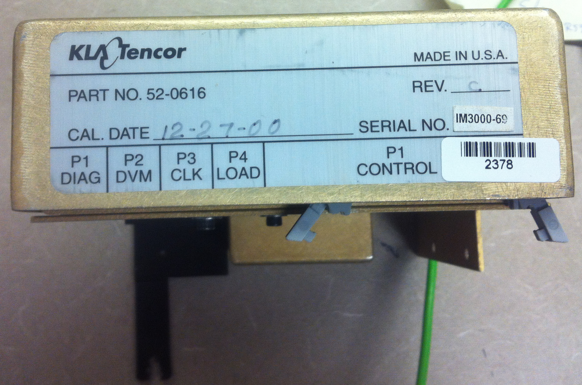
Side View: MEBox 52-0616
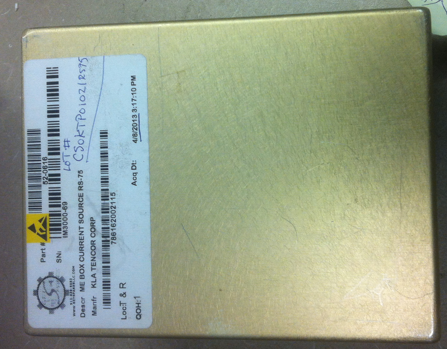
Top View: MEBox 52-0616
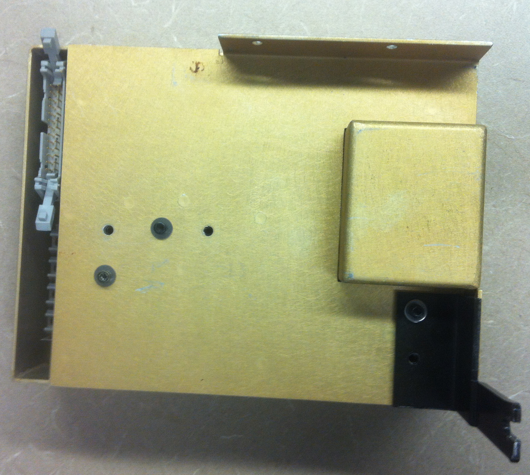
Bottom View: MEBox 52-0616