Dead Renogy LiFePo 12V Battery with BlueTooth

Once in a while we post slightly off topic findings that we think will be interesting/unique information for readers.  This post is about the very popular Renogy LiFePo battery with built-in Bluetooth.  Even though we don’t provide solutions for these batteries yet, we have recieved enough guestions about them that we got curious about what seems to be the common failure. This specific post shows the guts of a RBT100LF/P12-BT-US version, but there are versions that will have similar components.  These batteries are commonly used in off-grid applications to provide power to DC and AC devices using an inverter.

Failure Mode

The “dead battery” – This is when there is no output voltage, no bluetooth connectivity and the battery will not charge.  We don’t recommend repairing these batteries due to a fire risk, We decided to get into to understand the battery a little better.  Note that we kept a fire extinguisher near and will not put this battery back into rotation even after fixing the failed part.

Getting Into It

Not a lot of help we can provide here.  We cut, heated , cracked at the plastic and finally got the top to come off.  Send us a message if or make a comment if you find a better way to open a battery like this.  We will recommend it here.

Getting the top off is touch


BMS Failure, Cells or Wiring

In modern LiFePo batteries, you can break it down into three parts, Cells, Wiring and BMS.  Once the top is removed, the basic troubleshooting can start. Before getting started it is interesting to note this is a pretty high-quality battery, Prismatic cells..solid. Epoxy molded to keep things from moving around..solid.  No corrosion or dust since the case is sealed from the elements..not much to complain about.

If you took a good look at the picture above, you will notice that the voltage measurements and the wiring look good.  Since the cell voltages add to 13.2V and we don’t see any loose wiring, the likely culprit of the failed battery is the BMS.  There is a lot of information on the internet explaining what the BMS does, but basically, it makes sure the cells are balanced and it cuts off the connection to the LiFePo cells if there is a fault condition like too cold, cells are under-voltage, charger is trying to overvoltage the cells.  In this case, the BMS seems to be keeping the cells disconnected even though there are no real fault conditions.

What BMS Did They Use?

Well, the big clue are the red heat sinks.  To get to get it the BMS the way we did involved more caveman technics.  A dremel cutting tool is how we did it.

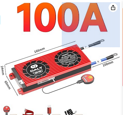
Again, please let us know if you have a better way to get to this.  With some more cutting and prying, we got the BMS out.  Sure enough, it is a standard Daly 4S 50A charge/100A discharge BMS you can get almost anywhere. We will follow up this post will a schematic extraction of the BMS.  Why?  No good reason.  These are so cheap it doesn’t make sense to try and repair it, but we will do it to understand why they are failing.  If you have read this far and actually took apart your battery to find a failed BMS, just buy a new one for about $50.

Not sure how long the link will be active, but this is the one…

https://www.amazon.com/DALY-LiFePO4-Protection-Balance-Battery/dp/B08PFPNNJG?source=ps-sl-shoppingads-lpcontext&ref_=fplfs&smid=A22QWF3YLLYB17&th=1

Hope geeking out on a LiFePo battery was fun for you.  It was for us, because we love digging deeper.  If you have any questions or general comments please email us at info@comvolt.com.


LCD Screens that are Repairable

Most LCD screens in industrial equipment are repairable.  Even with custom resolutions and touch screen interfaces.  Here are some examples..


KLA 90X0054 CMX15

NT30-ST131-V1

EST0220C05WNXE1

EEMP-0021X3

CEMP-0016 EEMP-0021X3

2-39-51930 2-39-61074 UT3-F1AE /DSS1-A

2-39-51930 2-39-61074 UT3-F1AE

Email info@comvolt.com if you need help with any industrial LCD screen

Fanuc 10.4″ A02B-0265-C071
Fanuc 10.4″ A02B-0281-D082
Fanuc 10.4″ A61L-0001-0163
Fanuc 10.4″ A61L-0001-0168
NEC 10.4″ NL6448BC33-49
Sharp 10.4″ LM64C350
Sharp 10.4″ LQ10D36A
Sharp 10.4″ LQ10D32
Sharp 10.4″ LQ10D321
Sharp 10.4″ LQ10D367
Sharp 10.4″ LQ10D368
Sharp 10.4″ LQ104V1DG5A
Sharp 10.4″ LQ104V1DG51
Sharp 10.4″ LQ104V1DG52
Sharp 10.4″ LQ104V1DG61
Sharp 10.4″ LQ104V1DG62
Sharp 10.4″ LQ104V1DG81

Dainippon Screen DNS Spin Cup Origin Return

Video of a DNS Track spin cup running an origin return.  This is a working unit for reference.  If you are having trouble with you 60A or need parts, contact https://getsparesllc.com for expert parts and advice and the best quality repairs.


Partname Partcategory Description Oem Model Datefield Picture1 Price
CERB-1016 2-VC-15254-1 Slave Board Transport Station Controller DNS 60A
CESB-2011 2-VC-19075 Slave Board Spin control board. Station Controller DNS
CEYD-0015 2-VC-13743 Power Supply 60A Power Controller DNS 60A
EEMP-0021X3 LCD Main Display Panel DNS 60A
CEBB-1011 Slave Board Station Controller Board BAKE DNS 60A
CERD-0111 Axis Controller Old style axis controller for robot DNS 60A
AU3585N222 CESA-0014 Servo Amp Old servo for DNS X”A” style DNS 60A

AU3585N222 CESA-0014, CERD-0111, CEBB-1011, EEMP-0021X3, CESB-2011 2-VC-19075, CERB-1016 2-VC-15254-1, AU3585N222 CESA-0014 Servo Amp, CEBB-1011 Station Controller Board BAKE, CERB-1016 2-VC-15254-1 Transport Station Controller, CESB-2011 2-VC-19075 Spin control board. Station Controller, CEYD-0015 2-VC-13743-GSRPR, EEMP-0021X3 LCD DISPLAY

LB101 5V International Power Sources Testing

If your regulator doesn’t have this IV curve it has failed. Contact us for repair or replacement. Stay tuned for a post about making this IV curve with and automatic tester almost anyone can make themselves. This particular supply is mounted on a PCB labelled BA 001-5104-02 REV-A but yours might be mounted on another board.

IV curve for LB101 5Vdc 5000mA power supply
I V curve for good LB101 5V International supply
IPS_LB101_5V5A_BA001-5104-02
LB101 International Power Sources Precision Regulator 5VDC 5000mA

Jumper Descriptions on Little Giant BL1100 – ZWorld C-Programmable Controller

If you are doing a conversion form Zworlds little giant BL1100, start by understanding what the jumpers are and how they are connected to your application.  Your new design will be dependent on the settings and will likely only need a fraction of the capability of this BL1100 board.  We have seen some applications that use most of its functionality, but it is usually just a couple of IO ports and and communications ports…

Table B-4. Standard BL1100 Jumper Settings
Header Pins Description Factory
Default

J12

1–2

Connect for factory-default RS-232 or RS-485
programming mode, remove for run mode or
user-defined programming mode

Connected

6–10

CTC3 output drives CTC2

8–9

CTC2 output drives CTC3

6–11

CTC2 operates at 16X baud rate of z0

6–12

CTC2 operates at 16X baud rate of z1

8–11

CTC3 operates at 16X baud rate of z0

8–12

CTC3 operates at 16X baud rate of z1

9–11

CTC2 drives external clock at 1/16 z0 baud
rate

10–12

CTC3 drives external clock at 1/16 z1 baud
rate

1–2
J13

J14

J014

J15
J16
J17

SIO Port A to RS-232 (J8)

Connected

2–3

SIO Port A to RS-485 (J3)

3–4

ZIO Port 1 to RS-485 (J3)

1–4

ZIO Port 1 to RS-232 (J8)

1–2

SIO Port A to RS-485 (J3)

2–3

ZIO Port 1 to RS-485 (J3)

Connected

1–2

RX and TX clocks come from SIO

Connected

2–4

TX clock from SIO, RX clock from external
source via pins 3–4 of header J3/J301

1–2

SRAM smaller than 256K

2–3

SRAM 256K or larger

1–2

EPROM 32 K

2–4

EPROM larger than 32K

1–2

Connect to enable excitation resistors for
analog input signal conditioning op-amps

Connected

Connected
Connected
Not
connected

continued…

��������������������

������

Table B-4. Standard BL1100 Jumper Settings (concluded)
Header

Pins

1–2
J18

Factory
Default

Description

RS-485 three-state always enabled

Connected

2–3

RS-485 three-state controlled by PB0

none

RS-485 three-state always disabled

1–2

Connect to enable onboard +5 V power
supply, disconnect for external power supply

Connected

1–2

EPROM smaller than 256K

Connected

2–4

EPROM 256K

1–2

Write-protect upper part of EEPROM

2–3

Write-enable upper part of EEPROM

J22

1–2

Connect to enable watchdog timer

Not
connected

J25

1–2

Startup mode factory-default RS-232 or read
from EEPROM

Connected

1–2

Remote reset using RXC

2–3

Remote reset using CTSB

none

No remote reset

1–2

Connect to enable switching power supply,
disconnect for time/date clock to control
power supply

1–2

Output DAC to pin 1 on J5/J501

2–3

Pin 1 of J5/J501 is analog ground

1–2

Connects E to expansion bus J24 pin 52

2–3

Connects BATACT to expansion bus J24 pin
52

J31

1–2

Ties high-voltage driver SUB signal to ground
to keep it from floating

Connected

J32

1–2

Connect to control use of ENMI signal on
expansion bus J24 pin 9

Connected

J19
J20
J21

J26

J27

J28

J29

������

Connected

Not
installed

Connected

Connected
Not
installed


Example Code: How to 3D Print Your Own Stand-off’s for Electronics

Often times in electronic assemblies, printed circuit boards (PCB) are spatially separated from one another through the use of stand-offs.  These stand-offs are usually quite prone to breaking, especially if you’re replacing/repairing/generally manipulating the PCBs attached to them.

Finding a stand-off that perfectly matches the original equipment manufacturer (OEM) stand-off can be a real pain, if even possible.  Luckily, with the advent of 3D printers, you can print your own stand-offs to your own specs!

There is an array of software packages available for designing models to be printed by 3D printers.  We like OpenSCAD because it’s:

  • free
  • precise
  • easy-to-use (even with very limited programming experience)
  • PARAMETRIC MODELS

OpenSCAD allows the user to “script” their model to precise dimensions and positioning, as opposed to popular GUI software where the user “draws” the model with the computer mouse.  GUIs are fantastic for artistic models (e.g. miniature sculpture), but not so great for scientific/mechanical/structural objects like stand-offs, where the dimensions of every minor feature to the model make or break its usefulness.

Did we mention that OpenSCAD models are parametric? That means that you can define models according to variables rather than fixed numbers.

For example:  you want a small box to hold your keys.  This box (imperfect cube) only needs to be about 75 mm wide,  25 mm deep, and 50 mm tall (roughly 3 x 1 x 2 inches).  You write some code like  “…cube([75,25,50]);….”  along with some other stuff and that results in a box that’s the best size for holding your keys.

But you really like that box, and you wish you had one just like it, except bigger, to hold your shoes.  So you go write new code  “…cube([300,125,125]);…”.  But then you want another box to hold your silverware.  So you go write more code with those dimensions.

Well how about instead, you have one code file (e.g. box.scad) that begins by declaring some variables:

x = ;  y = ;  z = ;  …and then your line “cube([x,y,z]);”…

Now, you can simply open “box.scad” and change the numbers for x=, y=, z= at the beginning, and the code will automatically generate the box to those dimensions.

Obviously this isn’t the best example – it’s not hard to type “cube([##,##,##]);” multiple times.  But if you’re familiar with OpenSCAD (or any other programming), you know that the code is much more than one simple cube line.  The model you’re generating likely passes x,y,z dimensions into several functions/modules to render the final piece.  It’d be a total pain to hunt down all the functions that use the dimensions you want to change and manually alter them.  So that’s why we define those variables at the beginning and pass them into all our functions.  Then you can simply change the variables at the top of the code anytime you want to reuse it for a slightly different size.

BACK TO THE STAND-OFF

We promised some example code.  So here it is, albeit extremely simple:

r = 5; h = 20; thickness = 2;

difference(){

cylinder(r=r,h=h);

cylinder(r=r-thickness,h=h);

}


Simple stand-off generated from the above code in OpenSCAD

Simple stand-off generated from the above code in OpenSCAD

If you download OpenSCAD, you can copy-paste this code right into the editor to make a simple stand-off.  Note that simply changing the numbers for radius, height, and thickness is all that’s needed to scale this stand-off to your liking.

There are a ton of resources out there on the internet to assist you in learning 3D modeling.  But, if you need a specific model and lack the time/will to design it yourself, email info@comvolt.com for any inquiries!

Controls Parts List for DNS 80B

Trouble finding the right part number for your DNS 80B part?  Look no further!  We scanned and OCR’ed the official Dainippon Screen Parts List for your convenience. Peruse the results below.  Contact www.GetSpares.com for replacement or repair solutions on the parts you need.

DNS 80B Control Units Parts List 1/3

DNS 80B Control Units Parts List 1/3

DNS 80B Control Units Parts List 2/3

DNS 80B Control Units Parts List 2/3

DNS 80B Control Units Parts List 3/3

DNS 80B Control Units Parts List 3/3

SERVICE ‘PARTS LIST (80B).x1s Z§_,_C_Qnj’__r_Q_I_U_n_i_t

REV.5.1 00.09
No A PARTS NAME APPLICATION TYPE PARTS No. DEL. MANUFACTURER REMARKS DIV. REV.
1 Indexer board ID-A EEDC-0011 2-VC-19089

2 Indexer board ID-A EEDC-0012 2-VC-34410 4

3 IF-B board (Type 1) IF-B EEIB-O01 2-VC-18166 1
14 IF-B board (Type 2) IF-B EEIC—OO1 2-VC*19284 1
5 IF-B board IF-B EEIC-0012 2-VC-19284-2 4
6 Transport board Transport unit EERC~O012 2-VC-19090-1 3
7 Spin board Spin EESC-0012 2-VC-19115

:3 Bake board Bake EEBC-0012 2-VC-19116

S9 Bake board Bake EEBC-0013 2-VC-34409 4
10 EEW board DEEW 2-VC-18987 1
11 EEW board DEEW EEUC-0013 2-VC-18987-4 4
12 EEW board DEEW EEUC-0014 2-VC-18987-5 4
13 EEW board DEEW EEUC-0015 2-VC-18987-6 4
14 EEW board UEEW EEEC-O02 2-VC-16147-2 1
15 Spin IFC board I Spin EESD-O01 2-VC-16027

16 EBR IFC bard Spin EESD-O11 2-VC—17102

17 Bake IFC board Bake EEBD—OO1 2-VC-16010

18 DS-LAN board *1 Main controller CEML-0014 2-VC-10751-3 3

19 DS-LAN board *1 Main controller CEML-0014 2-VC-10751-4 5
20 DS-LAN board *1 Main controller CEML~0O16 2-VC-10751-5 5
21 Parallel I/O board *1 Main controller CEMI-0011 2-VC-09977-1
22 RAS board Main controller FC-9801-06K 2-39-48605 NEC gg;380lB/2
23 Simplified RAS board Main controller PC-9821KE-E06 2~39-59409 NEC 5
24 Main controller FC-9821X/2 2-VB-25463
25 Main controller FC-9821X/2 2-VB-25463
26 HD adapter Main controller FC-9821KA-E01 2-39-59405 NEC 5
27 Hard disk drive Main controller §Cgg8fi$XA-HD1 2-39-59406 NBC 5
28 Copy board *1 Copy for main panel CEMG-O01 2-VC-20712 2
29 Copy board *1 Copy for main panel CEMG-0021 2-VC-24889 3
30 Station controller STANDARD (20 SLOTS) EEYC-0011 2-VC-20626 2
31 Station controller 28 SLOTS TYPE EEYC-O111 2-VC-20627 . 2
32 Station controller 11 SLOTS TYPE EEYC-003 2-VC-34399 5
33 GEM controller EEMZ-001 2-VC-25207-1 3
34 GEM controller EEMZ—0O11 2-VC—25207-2 5
35 1/0 unit box Main controller EEMH-001 2-VC-16705
36 Heater controller Bake unit(Max.8 HP) EEBH-0011 2-VC*162l7-1

37 Heater controller Bake unit EEBH~6011 2-VC-34885 CE TYPE 5
flmwm‘ 38 Servo amplifier Spin motor drive AU6356N20 2-39-53462 3
. 39 Servo amplifier Spin motor drive (8OB) EESA-0O1A1 2-VC-16396-2
40 AC power supply Primary AC power input/ EEPH-001 2-VC-16214
Secondary power output
UPS *l*2 Main controller back-up PS500 2-39-55593 HEIAN ELE §;fg“f$fHmJ%Ei 3.1
41 . 121368. (There is 5 UL
label on the backside
of the main body.)
42 Main panel EEMP-0013 2-VC-21746 2
43 Main panel Motor—drive EEMP-0112 2-VC-21747-1 2
44 Main panel Motor-drive EEMP-0113 2-VC-28117
45 Portable main panel EEMP-0212 2~VC-21717 2
46 ID-A panel ID-A EEDP—O01A 2-VC-14786-7 5
47 Maintenance panel ‘ *1 Spin unit CESP-0017 2-VC-10752-6 3
48 Maintenance panel UEEW EEEP-001 2-VC-17848-1 3
49 5 axis motor driver I EEKB-0011 2-VC-26961
50 8 axis motor driver ID—A/Transport Unit EEKA-001 2-VC-15485
51 8 axis motor driver ID-A/Transport Unit EEKA-0011 2-VC~23936

PORP (Incl. Printer) Edit Recipe on Portable
Personal Computer
Book type Personal comp. PC-9801NS/T40
Memory Card (8MB) RCS-8000
52 Application Software PS-98-1002-32 Ver.3.3D
Cable PORP-Printer PC-9801N-19
Printer PC-PR150N
PORP (Not incl. Printer) Edit Recipe on Portable
Personal Computer
Book type Personal comp. PC-9801NS/T40
53 Memory Card (8MB) RCS-8000
Application Software PS-98-1002-32 Ver.3.3D
Cable PORP-User’s Printer PC-9801N—19
54 EBR motor driver EBR CSD5807N-P 2-39-46547
CP power supply unit Cooling plate MR-2015 fig; 2-39~45432
‘K 56 CP controller Cooling plate FRD-4 1 2-39-45431
57 Chemical temp controller INR-244-402 2-39-45751
58 Circulator Chemical temp controller INR-244—404 (2oov) 2-39-45750
59 Circulator Chemical temp controller INR-244-406 (220V) 2-39-48373
60 Panel Chemical Temp Controller INR-244-403 2-39-48374 1
61 WCDS controller *1 For photoresist CECC~4012 2-VC-19786-1 2
62 WCDS panel *1 For photoresist CECP-001 2-VC-14144-1 2
63 Air elimination control. For photoresist PDS-1602 2-39-48738 2
*1
64 Air elimination panel *1 For photoresist PDS-1520 2-39-47429 2
65 Battery unit UPS Type BT-2-48(2Ah-4 48V) 2-39-58575
66 Fuse UPS Type (UL) TSC-8A 2-39-58576 s. 0. C
67 UPS with a Cable Main controller back-up CEMD-0012 2-VC-09974-1 HEIAN ELE
68 Video measure sensor DEEW EEUE-001B 2-VC-30392 Z4LC-CD2 TYPE 3.1
controller
Video measure sensor DEEW EEVE-001 2-VC-18989 3X2CA—PLC8 TYPE 4
69 controller
*1 Common to 80A
*2 back-up time comes to be shorter by degrees because the inside battery getting old.

Contact www.GetSpares.com for replacement or repair solutions on the parts you need.

Brooks Automation VCE Controller 001-4130-03

GetSpares.com has these control modules in stock and ready to ship.  The Brooks Automation VCE Controller 001-4130-03 is used in a large array of semiconductor fabrication equipment.  Get the replacement part you need from GetSpares.com today.

Brooks Automation VCE Controller 001-4130-03

Top view: comm and drive ports

Brooks Automation VCE Controller 001-4130-03

Side view: power and drive ports

Brooks Automation VCE Controller 001-4130-03

Side view: label